Electronic Devices
Meet Your Teacher | Assignments | Handouts | Class Bulletin Board | Related Links | Syllabus | Contact Me
Assignments
Your first assignment at your new job is to design (using available parts) a 12.0 volt regulated power supply, which will be used to test products. You are told that the equivalent load RL (min) of the products is 300 ohms ± 5%, and that the power supply must have a load regulation of better than 4%. You check with the plant electrician who assures you the nominal line voltage is 120V ±5%. Some quick calculations on the data you have so far tells you that the line voltage V (prim) will be 114V at the lowest and 126V at the highest. The load will be 285 ohms min. and requires approximately one-half watt of power. (P = V²/R)
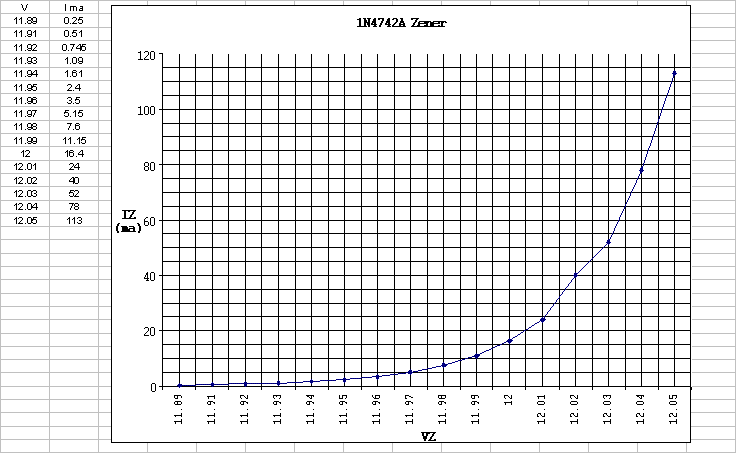
You know that at the maximum load condition of 285 ohms the zener current will be minimum and needs to be > IZK. You can assume this condition will usually be satisfied if the minimum voltage (VIN (min)) applied to the zener circuit is slightly higher than Vz at IZK. Usually, VZ at IZK is a few hundred milli-volts less than the rated Vz (12 volts in this case). Understanding that the efficiency of your circuit depends on this voltage being as low as possible you decide that you will base your design on a VIN (min) of 13 volts. You also decide that your supply will have a 1% ripple at the input to the zener circuit. The diodes you are using in your full-wave bridge with capacitor input filter each have a listed forward voltage drop of 0.775 volts at the expected load current giving a total loss VF of 1.55 volts. Adding this to 13 and multiplying by 0.707 = 10.288 volts + (ripple (pp) / 0.577see note) = 10.513 volts, the minimum rms secondary voltage V (sec) that will be required with the primary line voltage at it's lowest, so
turns ratio = 114/10.513 = 10. 84
at 114 V (prim) min, V (sec) min = 10.513 volts rms
at 120 V (prim) nom, V (sec) nom = 11.066 volts rms
at 126 V (prim) max, V (sec) max = 11.62 volts rms
Note: I arrived at 0.577 by taking the reciprocal of the square root of 3. It seems this is the magic number for a saw-tooth wave like ripple.
VIN (min) = (V (sec) min x 1.414) - VF - [(ripple (pp) / .577)]
VIN (min) = (10.513 x 1.414) - 1.55 - (0.225) = 13.09 volts
VIN (min) = 13.09 VDC
VIN (max) = (11.62 x 1.414) - 1.55 - (0.2489 see note below) = 14.63 volts
VIN (max) = 14.63 VDC note: 114 V to 126 V is a 10.53% increase so it is reasonable that this value would increase by that same amount.
Now a value for R is calculated using the equation:
R = VIN(min) - VZ / (IZK+ IRL (max))
R = 13.09 - 12 / (500 uA + 42 mA) = 25.95 ohms.
R = 25.95 ohms.
The approx. wattage rating of R can be determined from:
RPD = (VIN (max) - VZ) squared / R
RPD = (14.63 - 12) squared / 25.95 = 267 mW
RPD Å 267 mW
The approx.wattage rating of the zener can be calculated from:
ZPD = VZ x [(VIN (max) -VZ) divided by R]
ZPD = 12 x [(14.63 - 12) divided by 25.95] = 1.22 watts
ZPD Å 1.22 watts (two 1N4742's in parallel should work)
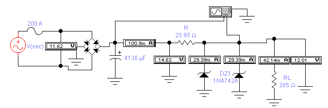
We can approximate the total current or IT at VIN (max) from:
VIN (max) -VZ (nom) divided by R
14.63 - 12 divided by 25.95 = 101.349 mA
IT at VIN (max) Å 101.349 mA
We can approximate the current through RL or IRL from:
12V divided by 285 ohms = 42.105 mA
The sum of the two zener currents would be IT - IRL = 59.244 mA with the current through each zener one-half this = 29.622 mA
IZ or the current thru each zener at VIN (max) Å 29.622 mA
The voltage across R or VR is VIN (max) - Vout at IZM
14.63 - 12.01 = 2.62 volts
VR = 2.62 volts
The total current or IT at VIN (max) = VR / R
2.62 / 25.95 = 100.96 mA
IT = 100.96 mA
R||ZR = Vout at IZm/ IT
12.01 V / 100.96 mA = 118.96ohms
RL||ZR = 118.96 ohms
The RL you use in the ripple equation will be
RL (ripple eq.) = R + RL||ZR
25.95 + 118.96 = 144.91 ohms
RL (ripple eq.) = 144.91ohms
The next step is to use the ripple equation to find what value of capacitor will be needed to satisfy the 1% ripple, which at 14.63 volts Vr(pp) = 146.3 mV pp.(multiply this by 1.414 before you enter it into the ripple equation) Vr(pp) = 206.87 mV. Using V (sec) max, VP (rect) = 14.88 volts, and 144.94 ohms for RL. You calculate that a 4,136 uF is required.
C = 4,136 uF
This is the circuit at VIN (max)
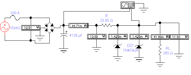
This is at VIN (min)
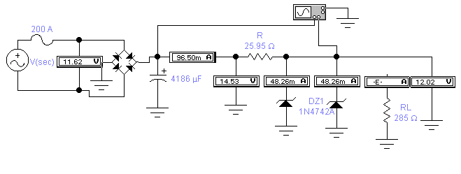
Here the load RL is disconnected at VIN (max)
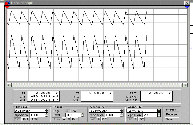
The ripple at VIN (min) is approx. 70mV (pp)
The upper waveform shows the ripple across RL
approx.11 mV (pp)
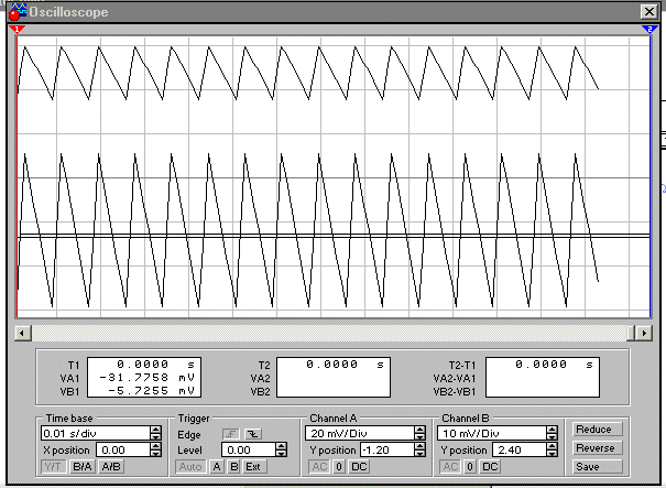
Lower waveform is the ripple at VIN (max).
Approx. 150mV(pp)
The upper waveform is the ripple across RL
approx. 2.2mV(pp)
1.When are the Zeners dissipating the most power? VIN (max), VIN (min), or RL disconnected at VIN (max).
2.When is R dissipating the most power?
3.The problem with the Zener regulator is its inefficiency. Calculate the efficiency in % at: VIN (min) ________% VIN (max) ________%
4.Calculate the load regulation ________%
5.Calculate the line regulation _______%
6.What minimum PIV rating can be used for the full-wave bridge?
7.If the diodes have an IFSM rating of 100 amps what Surge resistance Rsurge would you need to add?
8.What value slow-blow fuse would you need to protect the primary if the transformer is rated 12.6VA?
Be sure to use V prim (max) in your calculation.
9.Would the % ripple increase or decrease if a lower value of RL is used?
10.Calculate the % error between calculated and measured values:
% ripple _______% error V OUT at IZM ____________% error